Technologies
Delivering tomorrows marine energy solutions, today.
A vessel is an energetic ecosystem where, by combining zero emissions technologies, the sum becomes greater than the whole of its parts, with technologies supporting each other to reduce costs and increase efficiencies throughout the system, creating a Virtuous Circle of complementary energy efficiencies
Wind reduces energy requirements as well as allowing power to be brought back into the ships energy storage system (ESS). An extensive ESS allows power to be topped up under way, reducing bunkers, fuel costs and the volume of on board space dedicated to fuel storage, all but eliminating the cost and volume issues that are the biggest hurdle when considering green hydrogen as a marine fuel. Green hydrogen, used in energy-efficient hydrogen fuel cells, can act as a range extender when there is not enough wind or if the ESS has been depleted. Hydrogen propulsion can be used, for example, to propel a ship out of the doldrums or out of a storm and into more favorable wind conditions.
Batteries & ESS
Marine batteries are modular containers of one or more cells in which chemical energy is converted into electricity. They deliver instant power up to multiple MWh and have the greatest energy efficiency of any fuel or energy storage system. When used as an electric hybrid solution in combination with other fuels, marine batteries can optimize energy efficiency resulting in lower fuel consumption, reduced emissions, and reduced maintenance costs. Marine batteries increase safety, as well as allowing zero emissions maneuvering in ports. Because Marine batteries have zero noise and no moving parts they create no sound or vibration either onboard or in marine ecosystems. Due to rapide technology developments they can provide an ever increasing range of zero emissions propulsion.
In marine applications where safety, reliability and cost are the most important parameters, batteries provide compact and efficient main or auxiliary power.
In fully electric or electric hybrid Ships, marine batteries compliment hydrogen fuel cells and wind propulsion to deliver maximum efficiency in zero emissions propulsion.

SHIFT Clean Energy
display:none
How do batteries work?
A battery is a container consisting of one or more cells, in which chemical energy is converted into electricity and used as a source of power.
An SHIFT battery can be configured in capacity from 26kWh to multiple MWh. (From SHIFT Clean Energy Solution)

Image courtesy of SHIFT Clean Energy
Ions move from positive (cathode) to negative (anode) during charging and reverse during discharging.
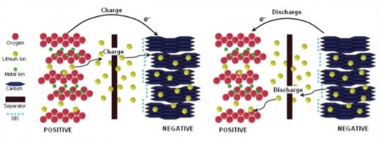
Image courtesy SHIFT Clean Energy
The Rated Capacity (C) of a battery is measured in Ampere Hours (Ah). It defines the size of the “gas tank” and is the current a battery can deliver from fully charged to fully discharged for a period of one hour.
The C-Rate is the rate of charge or discharge expressed as a function of the rated capacity. It Defines how fast the “gas tank” can be drained.
The rated capacity at the battery nominal voltage is expressed in Watt hours (Wh).
– Information from SHIFT Clean Energy Solution –
What is the lifetime of batteries?
Cell life is affected by:
- Charge Rate
- Maximum voltage
- Temperature
The cycle life is the number of complete charge/discharge cycles that the battery is able to support, and is used to measure battery lifetime.
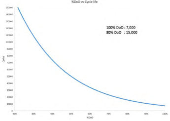
DoD vs Cycle Life – Image courtesy of Sterling PBES Energy Solutions
Charge Rate
The more charge/discharge cycles are completed, the lower the Depth of Discharge (DoD), or percentage of the energy removed from the battery.
Chemistry is a critical influencer of cycle life, and even then the detailed breakdown of the chemistry can alter the basic performance characteristics of the chemistry. Influencers like silicon can improve some aspects of performance in all chemistries, but they can also negatively impact aging, heat generation and degradation. Each chemistry relies on the integrity of its manufacturer and how “fit for purpose” it is for the markets we are applying it to.
Aging increases non-linearly with a higher charge rate (C-rate). So, the higher the C-rate, the fewer cycles the cell can undergo, reducing its lifespan.
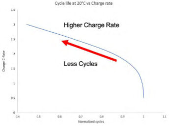
Cycle life vs C rate – Image courtesy of Sterling PBES Energy Solutions
On the other hand, Discharge rates are much less impactful than Charge rates, due to the chemical construction of the cells. On discharge, power is effectively ”allowed” to leave the battery unencumbered. We can discharge at very high rates of power; up to 10x the capacity of the system for short bursts.
But, in marine applications, we need to engineer for continuous power- and this means we limit our discharge with NMC batteries to 5C or 5 times the rated capacity of a system. SPBES can manage this generation of heat without compromising the life of the battery.
Maximum Voltage
Aging increases rapidly with higher cell voltage, even if voltage is reached only momentarily.
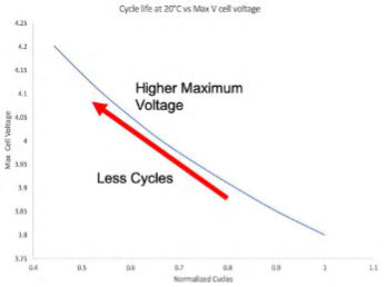
Cycle life vs Voltage – Image courtesy of Sterling PBES Energy Solutions
Temperature
Aging increases rapidly with higher cell temperatures during operation.
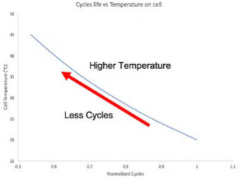
Cycle life vs Temperature – Image courtesy of Sterling PBES Energy Solutions
– Information from Sterling PBES Energy Solutions
What standards and certification exist to ensure battery system safety and quality?
Components and systems used in the maritime industry need to meet high requirements for safety and reliability.
For ships, leading IACS Classification Societies have produced certifications, standards and guidelines for operating with fully electric propulsion, hybrid-electric propulsion and Energy Storage Systems (ESS).
Information from SHIFT Clean Energy
What happens to batteries at the end of their use life?
To minimise the use of rare and precious metals, batteries should be optimised to allow for durability and recycling at their end of life.
Zero Emissions Services marine ZESPack is guaranteed to last 10 years. After 10 years, the capacity of the batteries is reduced by about 20%. Use of the ZESPack for another 10 years is possible in numerous other applications. At the end of this lifespan, the materials can be recovered and made suitable for reuse. Due to the long service life of the ZESPack, the system saves far more in emissions than it costs to build the batteries. (From Zero Emissions Services)
Image courtesy of Zero Emissions Services
The SPBES PlanB CellSwapTM is a retrofit process to rebuild the inside of a battery onboard a vessel. The cells in the core of the battery can be replaced when nearing the end of their life. If there is a requirement to service the cell stack, then the battery is removed from the ship and sent to the service depot. Since the cells can be replaced individually, only the cells at the end of their life need replacing instead of the entire battery. Other items, such as electronics and racking, are reused. There is no need for costly refit of existing hardware, only the consumable parts such as the cells are replaced.
SPBES offers support from commissioning to recycling, consisting of:
- Options for re-coring or recycling the system, including time and costs
- System decommissioning and arrangement for delivery of consumables to accredited recycling facilities included in the cost of the LPA
- A report of proof of recycling provided
– From SHIFT Clean Energy
What different types of batteries exist?
Lithium-Nickel-Manganese-Cobalt (NMC):
NMC chemistry provides the greatest balance of power, energy, safety, and overall performance compared to other lithium-ion technologies, including Lithium Titanate.
These batteries are suitable for powering fully-electric or hybrid-electric ships.
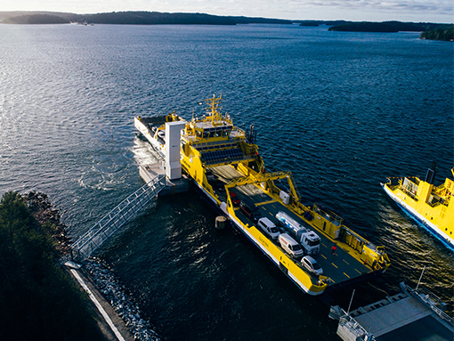
Image courtesy of SHIFT Clean Energy
Lithium-Titanate-Oxide (LTO):
Compared to other lithium-ion battery chemistries, LTO batteries tend to have an average power rating and lower energy density. They have an ultra fast charge and discharge capability, extremely long cycle life (>60,000+ cycles at 100% DOD) and are capable of a fast charge in <10 minutes.
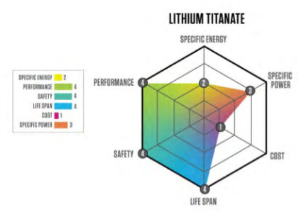
Image courtesy of SHIFT Clean Energy
These batteries are suitable for powering Dynamic Positioning, for example on offshore service vessels.
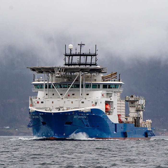
NTK Victoria – Image courtesy of SHIFT Clean Energy
Lithium Iron Phosphate:
Compared to the other lithium-ion technologies, LFP batteries tend to have a high power rating and a relatively low energy density rating.
Comparing types:
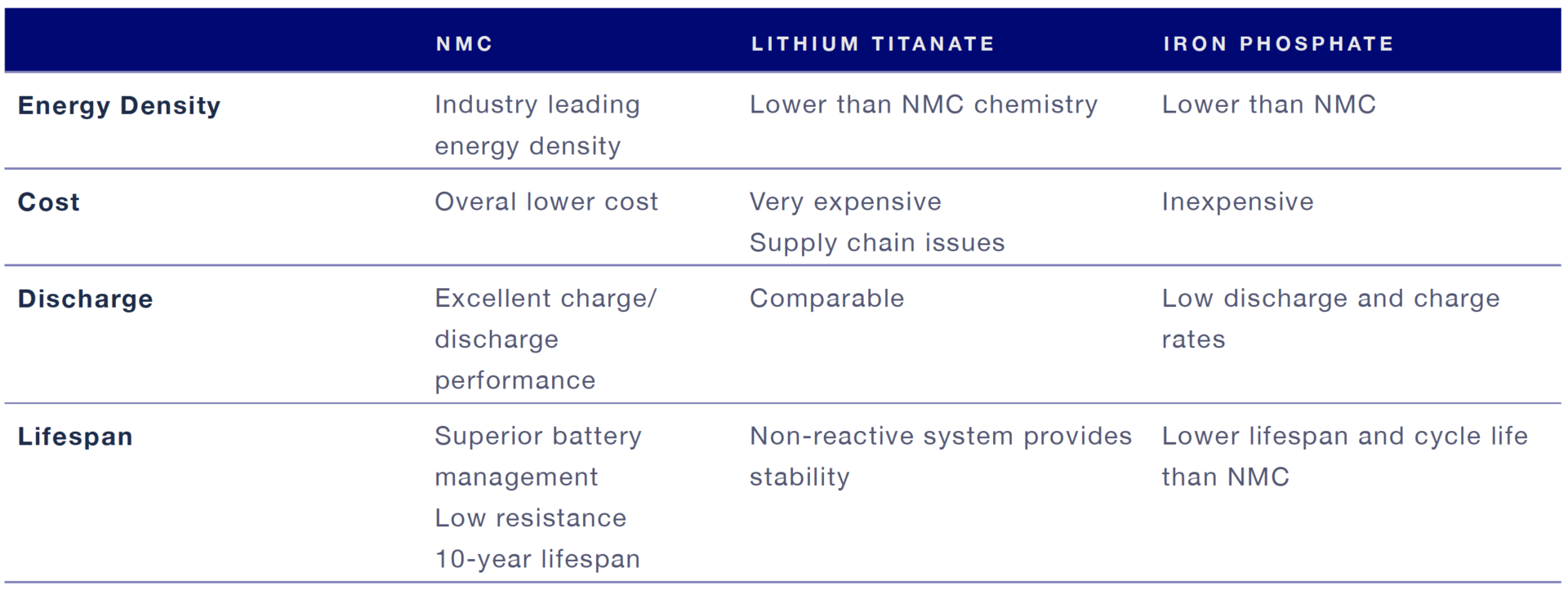
Image courtesy of SHIFT Clean Energy
Information from SHIFT Clean Energy
What is thermal runaway and how is it prevented?
Thermal runaway is a catastrophic overheating of the battery, causing a fire that generates toxic gases and risk of explosion. The fire can propagate between batteries and adjacent materials/structures. In a marine environment, this obviously causes great danger to the crew, the ship and any passengers on board.
Causes
There are a number of different ways thermal runaway can occur, as shown in the diagram below.
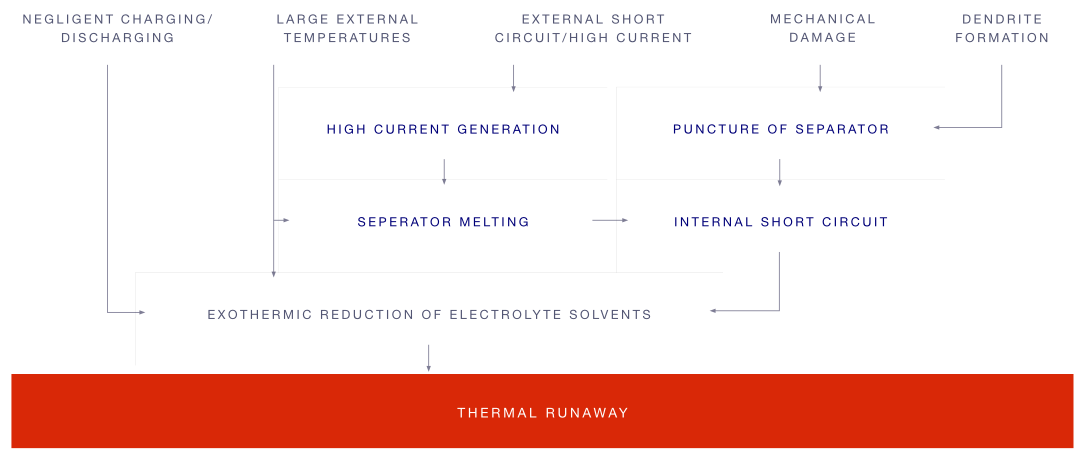
Image courtesy of SHIFT Clean Energy
Prevention
Maintaining low cell temperature at high power cycling or in a fault scenario is the key to lithium-ion safety. Keeping the internal temperature of each cell below the thermal runaway threshold ensures prevention.
For specific causes, the prevention measures below will remove the risk of thermal runaway.
|
Cause
|
Prevention
|
| Negligent Charging / Discharging | Include voltage upper and lower limits using BMS software and hardware sensing of each cell with direct trip line to DC breaker |
| High external temperatures |
Encase cell in cooling liquid to prevent heat from reaching the cell. Ensure cooling water is flowing at all times and prevent external fire from reaching batteries. |
| External Short Circuit / High Current | Encase cell in cooling liquid to prevent heat from reaching the cell. |
| Mechanical Damage |
Crush proof cell casing passing UN38.3 transportation tests. SPBES PlanB uses 19mm of aluminum armor protecting cell edges. |
| Dendrite Formation | Encase cell in cooling liquid to prevent heat from reaching the cell. If an internal short occurs from dendrite or manufacturing defect – the liquid cooling is able to remove more heat than a runaway cell is able to produce. Required coolant flow between 0.5GPM and 2GPM for RMS C rates between <0.1 and 3C. |
The Patented SPBES Thermal Management System is designed to prevent thermal runaway. Through thorough cooling of the cell, we facilitate the ability to use all of the available energy within the cell to its full potential- safely. By taking the heat away from the cell as it is created, we keep the cell temperature at ideal performance range (around 25 °C) and prevent the internal cell temperature from accelerating to the point where thermal runaway occurs.
– Information from SHIFT Clean Energy –
How is the safety of the crew and ship assured during battery installation?
The safety of crew and installation personnel is of utmost importance. A variety of hardware and integrated software protocols. These systems work together to protect the crew and system during the installation procedure.
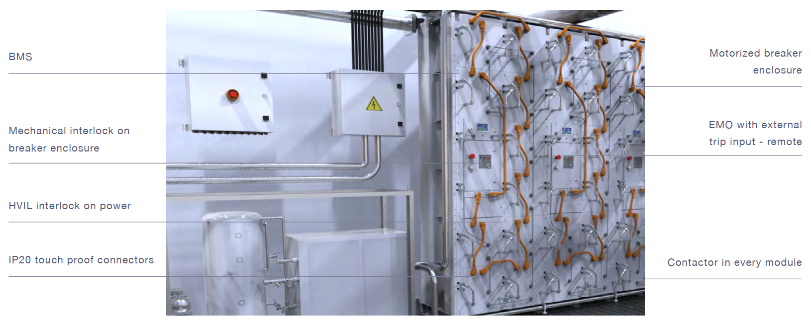
Safety mechanisms – Image courtesy of SHIFT Clean Energy
Safe voltage isolation is provided with:
- A contactor in every module
- No voltage during shipping
- Arc flash prevention during installation
- No voltage in an emergency for personal safety
- No hydrogen generation when submersed in sea water
- Use breaker to isolate string instead of contactor + fuse
During start-up:
- Motorized breaker connects ESS to the DC Bus
- BMS checks for correct cabling prior to enabling internal contactors and switching on battery
- Once setup complete, system waits for control command
- to connect to the DC Bus
- Final DC Bus connection performed by motorized breaker
- Ensures operator/installation safety and system isolation
– Information from SHIFT Clean Energy –
What is a Battery Management System (BMS)?
On a ship, a Battery Management System (BMS) is an integrated control and monitoring software which continually ensures the safe operation of a battery propulsion and/or storage system on board.
BMS software has large bandwidth and uses an ethernet connection with remote update capability and protocols to mitigate packet loss.
BMS carry out the following services:
• Ensures smooth and safe system start-up
• Provides current control to ensure the optimal charge/discharge rate for battery longevity
• Alarms and warnings including early identification of potential points of failure, hidden failures and failure prediction
• Remote monitoring and reporting of battery performance to inform maintenance
Redundancy is provided using direct emergency stop controls for the crew, redundant power supplies for each string, Redundant Management Software and remote monitoring for onshore investigation of anomalies by the service team.
– Information from SHIFT Clean Energy –


Green Hydrogen
Hydrogen when used as a fuel in hydrogen fuel cells provides efficient, silent, zero emission power generation. Green hydrogen can power fuel cells to provide efficient, silent, zero emission power generation. Fuel cells convert hydrogen and oxygen into electricity and heat and emit only pure water. Because hydrogen fuel cells have zero noise and no moving parts they create no sound or vibration either onboard or in marine ecosystems.
Multi- Megawatt (MW) Fuel cells are currently being used to generate power in stationary applications with >1MW systems being used in port marine environments for over a decade. In maritime shipping applications, fuel cells have been used in seagoing vessels, including passenger vessels and submarines for over 30 years.
In general, modular Multi-MW PEM fuel cell systems are composed of fuel cell stacks with a single balance of plant. The current maximum power rating for marinized fuel cell systems is over 200kW. These can easily be connected in parallel to a DC or AC grid to supply greater than 6MW with a high level of redundancy. These systems are built with state-of-art technology and commercially available equipment. Larger fuel cell stack and module power ratings of over 20MW are expected to be on the water in 2-5 years due to increased power density and expanded economies of scale. This will also drive down costs per MW by developing smarter technology, production methods and larger standardized sizes.
PEM fuel cell technology is the only commercially available option of maritime fuel cells today. Decarbonizing the maritime industry must start today and not wait another 10 years, to find a solution that might be better. It is key to continue developing and realizing maritime applications in ships, gaining extensive operational experience of today`s technology, focusing on developments and investments, to realize the most effective way forward, bringing down costs and increasing the uptake of zero emission propulsion.
display:none
How do Proton Exchange Membranes (PEM) work?
PEM fuel cells are electrochemical devices capable of directly capturing, in electrical form, the major portion of the chemical energy from the reaction where hydrogen and oxygen (taken from the surrounding air) form water. Fuel cells create electric energy and heat from using hydrogen as a fuel and air with only water as the only emission. (From PowerCell Sweden AB)
The total reaction 2 H2 + O2 → 2 H2O is divided into to main reactions:
At the anode (hydrogen side): 2 H2 → 4 H+ + 4 e–
At the cathode (air side): O2 + 4 H+ + 4 e– → 2 H2O
(From Nedstack Fuel Cell Technology BV)
This is achieved by dividing the reaction in two different reaction chambers connected via a proton stream over a proton conducting membrane and an electrical circuit where most of the energy released in the reactions is used to drive different types of electrical equipment. (From PowerCell Sweden AB)
The cathode reaction O2 + 4 H+ + 4 e– → 2 H2O generates water at the side of the fuel cell where air is present. Oxygen reacts at the cathode, while nitrogen acts an inert obstruction, preventing easy access of oxygen to the catalyst. The water produced by the reaction tends to form droplets, obstructing the flow of air to the cathode. For a stack current of i.e. 120A, the flow of air must therefore contain twice as much oxygen as the consumed quantity. Produced water is harvested with a condenser. This pure water is available for humidification of hydrogen and air, or the thermal energy of the warm water can be employed for useful purposes or drained.
The anode reaction 2 H2 → 4 H+ + 4 e– is facile and draws hydrogen to the fuel cells. Before entering the stacks, the hydrogen is humidified. At the outlet of the stacks the concentration of water vapor is higher than at the inlet, due to the consumption of hydrogen inside the stacks. The increased concentration of water causes the formation of droplets. An excess of hydrogen compared to stoichiometry is required to remove these droplets. Nedstack uses a minimum excess of hydrogen of 25%. The excess hydrogen is recirculated. (From Nedstack Fuel Cell Technology BV)
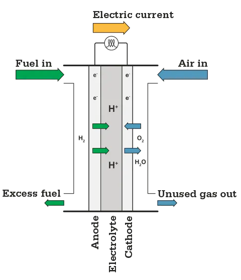
Fuel Cell Diagram – Image courtesy of PowerCell Sweden AB
The PEM-membrane is a thin film made of PFSA (Per Fluor Sulfonic Acid). The ionomer in the electrodes also consists of PFSA. PFSA possesses a backbone of PTFE-polymer with side chains to which sulfonic acid (SO3H) is attached. The membrane allows protons to pass but is impermeable for electrons. The membrane must be saturated with water in order to act as a proton carrier. The combination of water and sulfonic acid allows H+-ions to pass the membrane, so humidification of the membrane is essential. The membrane is also weakly permeable to gasses like hydrogen, oxygen, and nitrogen. During operation the main component of the air diffusing from the cathode (oxygen side) to the anode (hydrogen side) is nitrogen since oxygen will react under way with the protons.
The Membrane, Electrodes, and Gas Diffusion Layers (GDL) constitute the Membrane Electrode Assembly (MEA). When hydrogen and oxygen from the air are present a potential difference of about 1 V (maximally 1.23 V) arises across the membrane. The potential difference is less when current is drawn through the membrane. For a fuel cell current of 120A, commonly used in a PEM Power Plant, the voltage drops to 0.7 V at the beginning of life (BOL). This corresponds to an efficiency of conversion of hydrogen energy to electric power, or electric efficiency, of 56%, using the lower heating value (LHV) of hydrogen. The remaining 44% of the reaction energy which is not converted into electricity by the fuel cell is transferred to a liquid cooling media where it can be used for heating purposes. During the life of the fuel cell the electric efficiency will decrease and the thermal efficiency will increase to allow for a continuously high combined system efficiency.
– Information from Nedstack Fuel Cell Technology BV –
What is a fuel cell stack?
Several unit fuel cells are arranged in series into a so-called fuel cell stack to match voltage and power levels required in different applications. (From PowerCell Sweden AB) Such PEM-stacks are the building blocks of larger fuel cell systems. (From Nedstack Fuel Cell Technology BV)
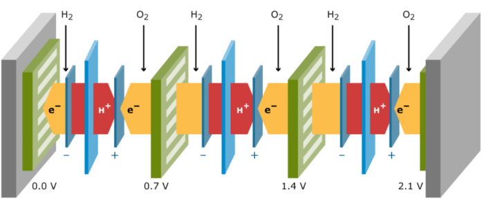
Fuel Cell Stack – Image courtesy of Nedstack Fuel Cell Technology BV
A fuel cell stack is in itself a completely passive component which needs to be integrated into a fuel cell system to generate power. (From PowerCell Sweden AB)
How do fuel cells work on a ship?
A fuel cell stack will not operate stand-alone, but needs to be integrated into a fuel cell system to generate power. On a ship, this is called marinisation.
In the fuel cell system, different auxiliary components such as compressors, pumps, sensors, valves, electrical components and control unit provide the fuel cell stack with a necessary supply of hydrogen, air and coolant.
The control unit enables safe and reliable operation of the complete fuel cell system.
Operation of the fuel cell system in the targeted application will require additional peripheral components i.e. power electronics, inverters, batteries, fuel tanks, radiators, ventilation and cabinet.
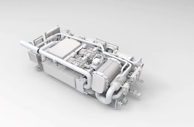
Marinised Fuel Cell System – Image courtesy of PowerCell Sweden AB
– Information from PowerCell Sweden AB –
What are the risks from fuel cell systems and how are these mitigated?
Degradation of materials
In the graph below, the variation of voltage with current is shown for a typical PEM stack. A fuel cell always follows the imposed load.
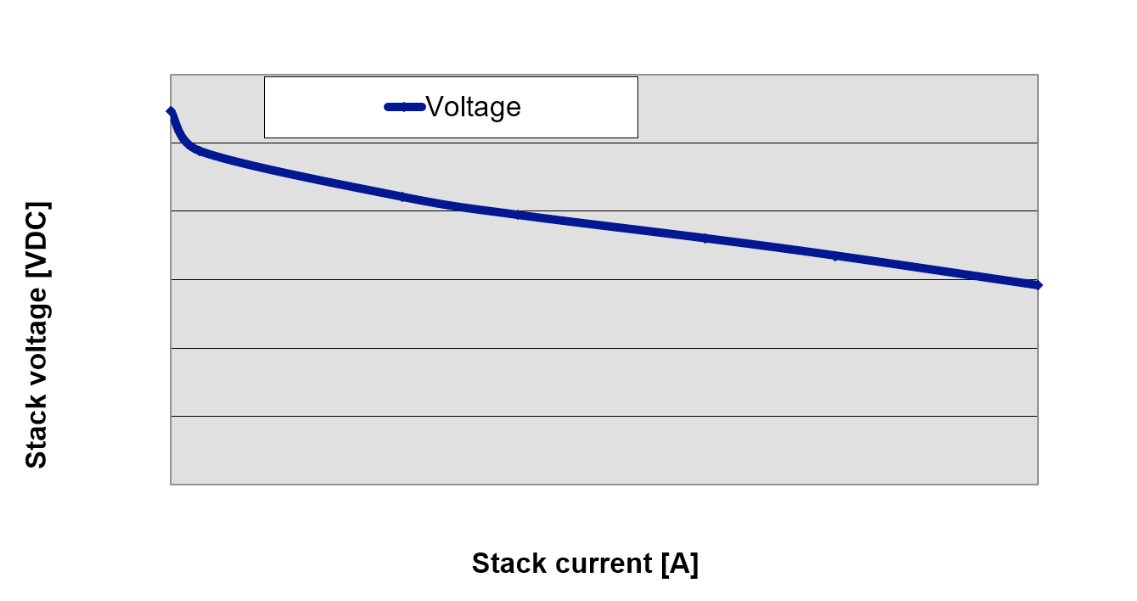
Stack Voltage vs Stack Current – Image courtesy of Nedstack Fuel Cell Technology BV
To follow this load, adequate hydrogen and oxygen must be present. If reactants are lacking, the fuel cell consumes materials of the electrodes, such as carbon, and damages itself.
Prevention is ensured by assuring the availability of hydrogen and air must before a load is applied. Cell voltage monitoring is installed to prevent damage when the load settings are too high. A group of stacks will stop automatically when the cell voltage on any stack in that group drops below a threshold value. (From Nedstack Fuel Cell Technology BV)
Constructing fuel cells with durable materials reduces risk of degradation and increases life span. For example, PowerCell’s unit cells consist of compact and lightweight metallic bipolar plates combined with durable and highly efficient membrane electrode assemblies. (From PowerCell Sweden AB)
Overheating
The PEM fuel cell stacks manufactured by Nedstack operate at temperatures around 65ºC. Excess heat generated during power generation is transferred by a cooling medium. This is pure water with an electric conductivity below 5 µS/cm. The water needs to maintain a low conductivity to prevent short circuit currents between individual cells. The demineralized water efficiently carries the generated heat. (From Nedstack Fuel Cell Technology BV)
What safety standards exist for fuel cells?
Design
A wide range of product and application-relevant standards to safeguard fitness-for-use exist for all relevant applications of fuel cells. The cornerstone of compliance is that all stack designs and the production system observe the IEC 62282-2 standard on the safety of PEM Fuel Cell stacks. Product designs should be independently verified and production systems should be designed to verify every stack by means of a standard compliant exit-factory inspection routine, as shown below. (From Nedstack Fuel Cell Technology BV)
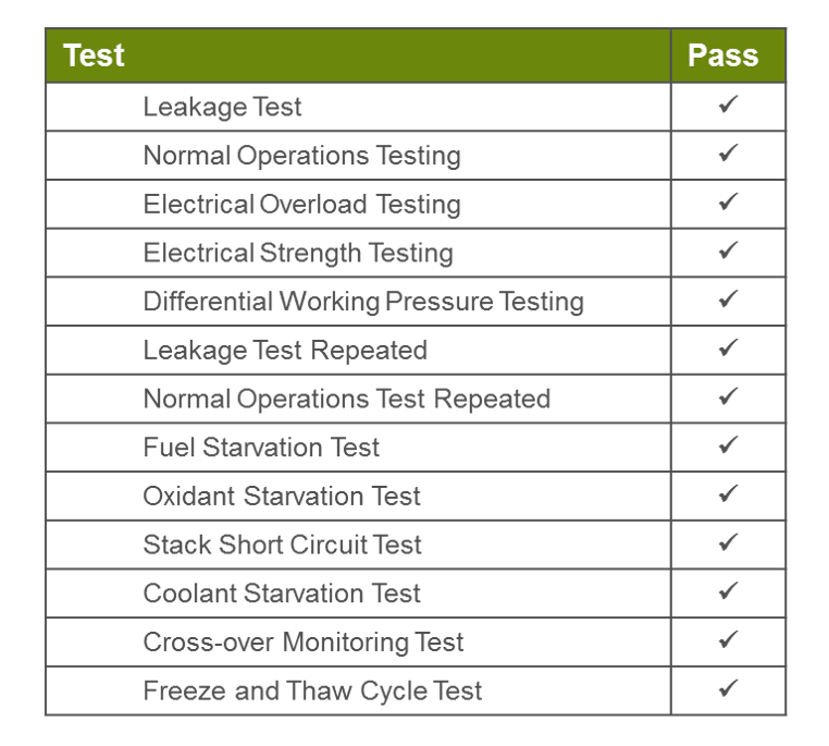
IEC 62282-2 Tests – Image courtesy of Nedstack Fuel Cell Technology BV
Use on ships
The use of fuel cells on ships is allowed by international conventions. In April 2022, the IMO approved the ‘Interim guidelines for the safety of ships using fuel cell power installations’. In addition, all major classification societies have rules or guidelines in place.
New developments and innovations in fuel cells, which may not be directly covered by the existing rules and guidelines can still be safely installed on board using the alternative design method in accordance with SOLAS Regulation II–1/55 for demonstration of an equivalent level of safety.
What are the benefits of PEM fuel cells?
Proton Exchange Membrane or PEM Fuel Cells are considered to be the most versatile type of fuel cells currently in production. They produce the most power for a given weight or volume of fuel cell. Because they are lightweight, have such high power-density, and cold-start capability, they qualify for many applications, such as stationary combined-heat-power, transport, portable power and even applications in space.
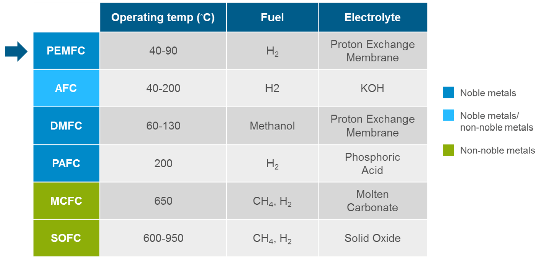
Fuel Cells Comparison – Image courtesy of Nedstack Fuel Cell Technology BV
Pure hydrogen-powered PEM Fuel Cells emit zero particulate matter, SOx or NOx, zero CO or CO2. They have long lifetimes (>20,000 hours) before refurbishment is required and they have a high power density.
Their low operation temperature makes them ideal for operation on ships, as well as being a proven technology with a strong track record in a large variety of applications. (From Nedstack Fuel Cell Technology BV)


Wind Propulsion
Wind propulsion technologies harness instant, free and renewable wind energy to propel vessels, reducing power demand by 20% or even up to 63% with route optimisation. They can be retrofitted and even folded away to ensure seamless and safe operations.
Wind propulsion technologies harness free and renewable energy from the wind to propel vessels. When a ship is designed with wind as the main propulsion the wind can provide > 80% of the ships energy requirements, depending on the ships profile.
Wind propulsion technologies convert wind energy into thrust, reducing fuel consumption, GHG emissions and air pollution. Modern systems are fully automatic, highly durable, require little or no maintenance, have minimal impact on daily vessel operations and require no port infrastructure to function. They can be deployed with any main propulsion system, reducing the load required for zero emission solutions like hydrogen fuel cells. In tandem with energy storage systems (ESS), wind propulsion is fully optimised, allowing for maximum efficiency as wind conditions change. When wind force exceeds propulsion requirements, excess energy can be brought into the ships ESS, increasing ships autonomy.
Most wind propulsion technology can be easily retrofitted and even tilted or folded away to ensure seamless cargo handling and safety in very high winds.
Types of wind propulsion technology currently on the market; Flettner rotors, soft sails, hard sails, towing kites, suction wings, turbines and hull forms.
display:none
How does thrust from the wind propel a vessel?
The resultant force that generates Thrust on a wind propulsor comprises of the wind pressure exerted perpendicular to the wind propulsor’s projected surface area and/or the aerodynamic force generated due to the pressure distribution difference around the wind propulsor shape.
For any direction of the incoming to the wind propulsor, a specific Lift and Draft forces is developed, the geometrical vector sum of which results in a Thrust force direction which propels the ship.
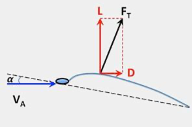
Thrust force (F) from wind direction (V) – Image courtesy of M. Fakiolas
The wind is comprised of air masses of a specific density (ρ) which varies with atmospheric pressure and temperature, flowing (u2) over the surface (S) of a specific coefficient of lift (CL) wind propulsor at specific relative angle to the wind propulsor z axis orientation, thus generating a Lift force (L) perpendicular to the surface geometric reference line.
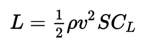
Lift force equation
The lift coefficient (CL) relates to the ability of a wind propulsor geometry and/or mechanical design or features (i.e. such as rotational speed for a flettner rotor or fan aspiration for a suction wing sail) to generate Lift.
The drag force is also dependent on the wing sail geometry and mechanical features while different shapes have different drag coefficients.
The variation of the angle of attack of the wind direction on a given wind propulsor has a direct impact on the lift coefficient and drag coefficient, and hence the lift, drag and thrust generation capability of a wind propulsor. For every wind propulsor geometry and function, there is always an optimal angle of attack that provides the maximum coefficient of lift.
The performance and efficiency of every wind propulsor type, size and technology is primarily determined from 4 factors:
- Surface area
- Relative velocity: wind speed and ship speed related
- Lift coefficient: surface geometry/sail mechanism/positioning related
- Drag coefficient: surface geometry/ sail mechanism/positioning related
– Information courtesy of Konstantinos Fakiolas book ‘Wind Propulsion Principles’, Edition 1 –
What are Flettner rotors and how do they work?
The wind propulsor type called ‘Flettner Rotor’ is a mechanically operated cylindrical sail installed vertically on the deck of the ship and rotates at certain speed range.
The name is coming from the German aviation engineer and inventor Anton Flettner who experimented on the idea of a rotating cylinder generating lift force inside an air stream, tested in both marine and aircraft applications during the 1920’s.
Rotor Sails are a modernized version of the Flettner Rotors and are considered as mechanical sails, currently installed and operating in RoRo, RoPax, product tanker and bulk carrier ships.
Main Components
- The Rotor Sail is mainly comprised of the below main components (Figure 3.1):
- The cylindrical Rotor
- The rotor Tower
- The Foundation with the bearings
- The Drive system (electric variable speed)
- The wind sensors
- The Power Control and Bridge operating panel
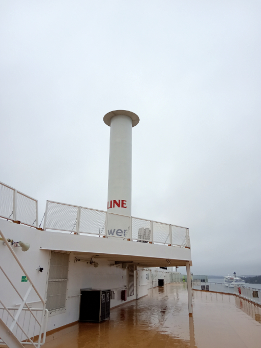
Flettner rotor on the Viking Grace / Source: D. Newman
The rotating cylinder is usually made of a laminated glass fibre and carbon fibre composite material.
The Rotors are utilizing a physical phenomenon called ‘Magnus effect’. When the rotor is rotating, a small boundary layer is formed around it, inducing a pressure differential between its opposite sides when it is exposed to an air flow (wind).
A resultant perpendicular to the wind flow force is generated and the maximum exploitation of the wind happens in beam reaching directions to the ship. The Rotor sail speed of rotation increases or reduces the thrust force magnitude.
The Rotors consume electrical power from the existing ship’s electric grid to rotate at their specified operating speed, usually 0 to 180 or 250 rpm. The power required for the rotor rotation can vary depending on the size of the rotor sail, the aspect ratio and the max RPM, ranging from 40 kW up to 160 kW. Usual dimensions of rotors are 18 to 35 m tall and 2 to 5 m in diameter.
The Rotors Sail normally operate in fully automatic mode, in a way that the operation starts and stops from the Bridge control panel. When the wind conditions are unfavourable then the rotors Sail can either rotate more slowly to mitigate unfavourable drag or completely stop.
Some rotors Sails can be tilted to decrease the air draught or moved along rails on deck to facilitate cargo handling operations.
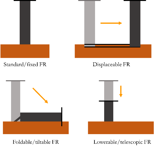
Types of Flettner rotor (FR) / Source: D. Newman
When placing multiple rotors Sails on deck, as far as practical and as far away from each other, with a general rule of thumb being that each Rotor should be located such that there is a minimum distance equalling the height of the rotor between adjacent rotor sails and nearby deck structures.
To install a rotor sail on deck, a foundation is needed to incorporate the housing needed for the main driver system and the lower bearings. A power supply and the remote-control panel on the bridge are required and auxiliary power to enable tilting-moving if necessary.
The material of the rotor sail is usually composite, thus the expected lifetime depending on the manufacturer material quality choices could be at or above 5 years, with some manufacturers reporting that with good quality material the design lifetime of the rotor composite can reach even up to 20 years.
– Information courtesy of Konstantinos Fakiolas book ‘Wind Propulsion Principles’, Edition 1 –
What are suction wings and how do they work?
Suction wings are wing sails with very large thickness and an in-built mechanical air suction mechanism.
Suction wing sails are currently installed on a number of general cargo vessels, bulk carriers, oil/chemical tankers.
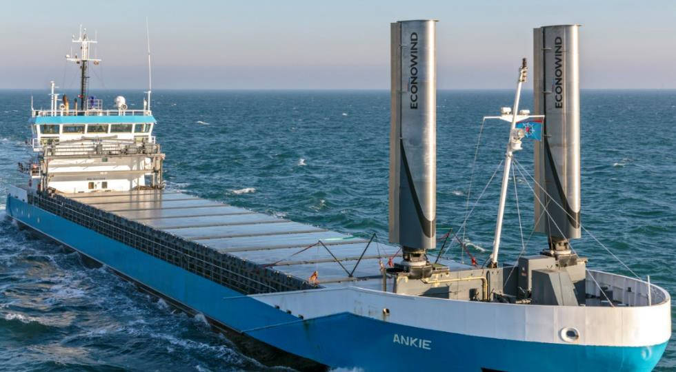
Econowind Ventifoils on MV Ankie / Image courtesy of Econowind
Suction wing sails are comprised of the below main components:
- Vertically installed wing incorporating the ventilator fan
- Ventilator system for the fan
- Folding mechanism (for folded systems)
- Hydraulic system & powerpack
- Control Panel and Electrical system
To control the airflow around the ‘thick’ foil-shape, a boundary layer suction is applied for which a one or more Ventilators needs to be installed inside the suction wing profile. At the leading edge (the ‘nose’ of the egg-shaped cross section) the airflow is accelerated leading to very low pressure on the top-left side of the profile and all along the suction-side.
It is an artificial way to reduce the drag coefficient of the wing profile while keeping the lift coefficient high, even as high up to 7-8 depending on the angle of attack and the suction efficiency. They sizes can vary between 10 up to 30 36m tall.
The suction wing sail can develop quite high lift forces without any self-rotation mechanism, with relatively compact dimensions. They are fully automated and can be foldable in case of unfavourable wind conditions or during cargo operations.
Suction wing sails can be installed either in a containerized form or with a flat-rack or fixed on the deck. When a containerized system is considered then it can be installed as a simple container unit by fixing the system with straps to the hatch cover and plug the system to a 400V/32A plug.
It is expected that certain maintenance will be needed on the main bearing, the ventilator fan, the flap motor and the hydraulics, with most components being familiar/similar to other usual ship equipment.
– Information courtesy of Konstantinos Fakiolas book ‘Wind Propulsion Principles’, Edition 1 –
What are towing kites and how do they work?
Towing kites are airborne paraglide-style devices attached to the bows that utilise wind thrust to pull a ship forward.
The main components of towing kites are:
- The flying kite, which is similar to a paraglider wing being elliptical in shape and geometry,manufactured of high strength fabric material and is inflated with air,
- The Control Pod, which is a mechanism that is connected between the towing rope and the Kite, and activates and controls the Kite motions through numerous suspension ropes connected to the Kite edges and interior surfaces,
- A towing rope which is a high strength synthetic material rope which incorporates also inside the signal/supply cables for the control pod functioning,
- A towing winch, which is a typical variable speed controlled electric-hydraulically operated marine type winch that releases or retracts the Kite at certain speeds, a reefing winch which is helping to guide the Kite on the docking position during retraction,
- An electrically operated telescopic mast which is extended for Kite launching operations and retracted when Kite is landed/docked back,
- Power pack needed for the electro-hydraulic parts operation and the Control Panels with relevant software and Bridge / Remote controls.
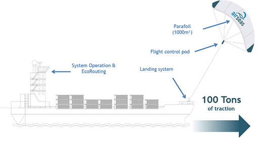
Diagram of AirSeas SEAWING towing kite / Image courtesy of AirSeas
In contrast to other wind propulsion systems, the propulsion Kite is airborne and operates away from the ship structure at altitudes of over 150m. The Kite needs a minimum wind speed to lift-off and then it can operate at smaller than lift-off wind speed.
The optimal performance and efficiency corresponding to normal flight conditions are achieved when flying within the Power Zone which has an elevation angle of 10 to 35 degrees from the sea level. When the wind conditions become unfavourable (i.e. headwind) the Kite comes in the neutral/parking position where no forward thrust is generated.
The optimal towing force to the ship is when the wind direction is in reaching course (side tailwind), rather than in running course (full tailwind), because of the apparent wind speed benefit (i.e. in running course the ship’s speed is deducted from the wind speed, hence the useable wind energy is less).
In operation, the kite moves in a dynamic figure of 8 movement to increase the apparent wind of the kite to more than 10-fold than that of the vessel. This way, the kite maximizes the traction force by flying fast into the incoming wind while towing the ship. With a relatively much smaller surface area compared to other on-deck wind propulsors, it can generate multiple times of thrust because of the dynamic movement. Furthermore, they operate at heights where the wind speed is double that at sea level.
Sizes of kites range from 20 m2 Kites to 1,000 m2. Selection for each ship project usually refers mainly to the Kite’s rope design load in kN while the maximum strength is much higher for safety reasons.
The kite is designed to operate fully automatically, from the moment it is unstowed and docked on the retracted telescopic mast until the time it is deflated after being docked back to the mast prior to restowage. This means that the crew intervenes manually to only unstore and connect the kite to the mast and then again during undocking and storage. The whole deployment process takes about 15 minutes.
In case of a power blackout, the kite has a 30-minute self-redundancy until the emergency generator is engaged. The winch is also designed to retract the rope of the kite much faster than usual during emergency conditions, with special consideration given to avoid entanglement with the propeller. A final resort emergency system is a pneumatic rope cutter, disconnecting the kite totally from the vessel.
Towing kites have relatively little impact on heel and yaw angles on the ship and have a positive contribution to the course keeping of the ship and it requires much less corrections on the rudder and much less rudder action than deck mounted systems.
Installation is located on the forecastle of the vessel aligned to the centre and requires no drydocking. A steel platform may be necessary to elevate the kite foundation if there is no space.
Depending on the utilization time of the kite, and the quality of the components, the surface material and the towing rope may represent a variety of operating hours replacement, counted in few thousands of operating hours. The rest of the system is a conventional winch and telescopic mast system as usually found in other marine applications.
– Information courtesy of Konstantinos Fakiolas book ‘Wind Propulsion Principles’, Edition 1 –
What are rigid/hard wing sails and how do they work?
Rigid wing sails resemble classic sails but are comprised of rigid materials so that the sectional profile of the Sail is more stable and resembles an aircraft wing in the cross section.
Wing sails are mounted vertically on the main deck and/or forecastle of the ship and operate under the same aerodynamic lift principles as an aircraft wing. Each wing has a specific aspect ratio (height/width) and wing profile geometry so that an as high as possible aerodynamic Lift force is generated.
In adverse conditions or at berth, wing sails can be furled/reefed telescopically or otherwise to remove unnecessary drag forces or air draft. All systems are designed to work automatically, thus by adjusting their wing sails orientation depending on the anemometer readings, while in unfavourable wind conditions there is an automatic function for reefing or furling.
Normal sizes offered by the system providers so far relate to a Wing Sail height of 20-30 37m and width 8-20m – or other tailor-fit intermediate sizes, while in case of a solo Wing Sail installed in the forecastle can be a bit higher when in full deployment – i.e 50-55m x 15m and 20-25m when reefed.
One issue with the wing sails systems, especially the ones which are equipped in more than 2 on board is related to how the IMO visibility and safe navigation rules are satisfied, which is still under review for case-by-case consideration at the moment.
Installation equipment other than the sail and structure includes an electro-hydraulic power pack for rotation, reefing and furling. A remote-control panel is usually installed on the bridge for system operation. Moving parts will need regular inspection, overhauling and maintenance especially of the wear and tear items (i.e. bearings, gaskets, etc).
– Information courtesy of Konstantinos Fakiolas book ‘Wind Propulsion Principles’, Edition 1 –
What are soft wing sails and how do they work?
These wind propulsors are similar to the rigid wing sails that are described above, the difference is that they do not have a rigid wing coverage surface material but a more soft one, so that Furling and adjusting of variable camber of the wing profile is possible.
The material of the soft sail is normally made of composite (polyester sailcloth or similar) for endurance in a marine environment, having certain flexibility for being compressed and reefed appropriately.
When the wind becomes unfavourable then instead of retracting, the wing sail is reefed and furled to reduce their exposure to the wind.
The aspect ratios per wing can vary from heights of 30-40m and width from 10-15m, depending on the design and the available space on board.
The requirements for the soft wing sails regarding the installation are mainly similar to the rigid wing sails as described previously, it would be expected an extra auxiliary mechanism to be installed for the furling of the sail cloth, either that be electrical or hydraulic or even pneumatic depending on the provider.
One differentiation regarding maintenance compared to rigid wing sails would be expected to be the soft cloth strength and durability, since such would be related to the operational hours on wind force exposure but also to environmental conditions, such as sun radiation, heat, cold, ice and humidity.
– Information courtesy of Konstantinos Fakiolas book ‘Wind Propulsion Principles’, Edition 1 –
What are soft sails and how do they work?
The origin of such a sail system for a commercial ship use is definitely derived from the yacht wind design experience and experimentation, with first square-rigged soft sail systems appearing since the 1960s.
One of the most reputable such introductions has been made from Dykstra naval architects who are specializing in yacht design and have developed the so called ‘Dynarig’ system which is an advanced automated deployed and trimming soft sail wind propulsion system.
The Dynarig system is comprised of free-standing masts where the soft sails are deployed on the rigidly attached curved yards, in a way to have no gaps between them as seen in traditional conventional soft sail system.
Operations for unfurling are done automatically from a remote control panel, and it takes about a minute to set a sail with setting one per mast at the same time, thus requiring about six minutes for the entire sail system to be hoisted. Rotation of the rig into the wind automatically if the ship starts to heel too much, with specific limits able to be set, connected to sensors such as anemometers.
With the Dynarig the ship can sail upwind at apparent wind angles between 33 and 36 degrees and managed also with change of mast direction through 100 to 105 degrees.
Soft sails need deck space for installing the mast, the foundation, and the rotating system with bearings. It is expected however that moving parts such as soft sail furling would need replacement depending on their operational use and the soft sail cloth as well.
– Information courtesy of Konstantinos Fakiolas book ‘Wind Propulsion Principles’, Edition 1 –
What wind conditions are suitable for wind propulsion?
The most attractive wind/wave combination for an effective wind propulsion takes place between 5-8 Beaufort (BF) scale, and for some ships which sail around 10-12kn even in BF 4. The Global wind probability chart has also shown statistically that the higher range of average global wind speeds (probability over 10%) happens around 5-8 m/s, which corresponds to BF 4-5.
Therefore, the slower the ship sails, the better global wind utilization she achieves over time.
The probability of wind speed is widely scattered globally. These phenomena generate the following possible problems related to the wind propulsion utilization in the oceans:
- Ship speed is critical for the wind propulsion energy harvesting capacity,
- Wind blow direction may not coincide or be synchronized with wave direction,
- Ocean currents may also act as an extra force to the hull of the ship, thus impacting either negatively or positively wind propulsion efficiency
Because of these factors, weather routing is also highly important for optimising the wind propulsion performance.
Global winds tendencies exist in local regions. For example, in Northern Europe and in specific in the Baltics and North Sea, the wind forces are more intense and more prevalent compared to the Mediterranean Sea, with the exception being the Aegean Sea in Greece and the Southern coast of France. Therefore, despite their possible smaller sea time utilization due to regional trading, small and medium size cargo and passenger ships may highly benefit from wind propulsion devices in certain regions such as North Sea and Baltic Sea due to their smaller size and required propulsion power.
– Information courtesy of Konstantinos Fakiolas book ‘Wind Propulsion Principles’, Edition 1 –
What is route optimisation?
Route optimization or weather routing predicts the optimal conditions for efficient sailing with wind propulsion devices, taking into account the instant/prevailing ocean wind energy potential to ensure minimum fuel consumption. Because of the complexity required of the application, a fully automated voyage optimization system coupled with the wind propulsion system and the main propulsion plant of the ship is needed. The resulting route may differ depending which wind propulsion device is installed, due to their different optimum wind conditions for maximum performance.
On board voyage optimization computers can be used in conjunction with accurate and real time weather forecast data, which will provide to the captain the best possible routing that would be optimal for ETA and for fuel consumption, or at least the best compromise of the latter.
Especially in large oceangoing voyages of over 3-5 days where the weather forecast uncertainty rises considerably, there can be methods to use stochastic optimization of the routes by combining real time weather data coming from such providers.
The application of wind propulsion technologies requires either more trained and competent captains or more integrated automation controlled ship power adjustments, wind propulsor functional parameters adjustments, weather routing and voyage optimization in a holistic way to ensure safety of navigation and reduction of fuel cost and CO2 emissions at all times.
– Information courtesy of Konstantinos Fakiolas book ‘Wind Propulsion Principles’, Edition 1 –